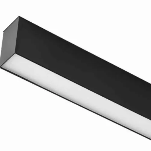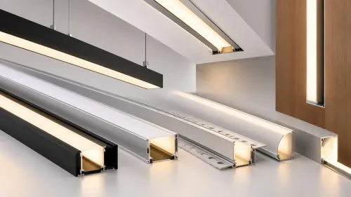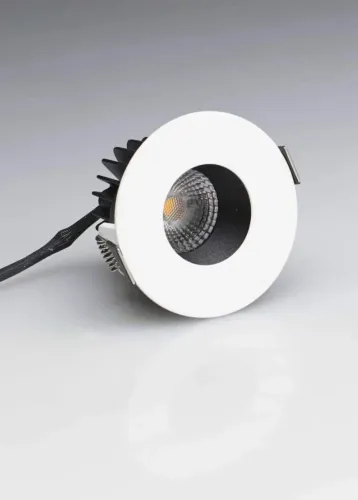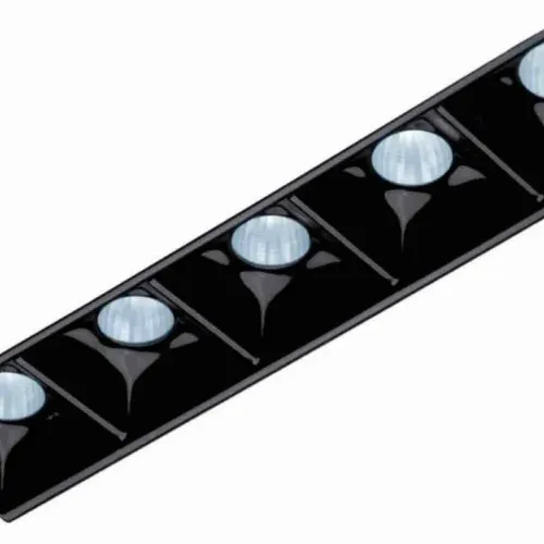
A dark, flickering, noisy, dim, or mechanically stuck LED zoomer light can fail in the supply, driver, LED module, track connection, optics, or mounting. By the end, you will have a safe fault-isolation sequence, the key meter checks, and a clear basis for repair, replacement, or calling an installer.
Key takeaways
- Switch off the MCB and confirm isolation before opening the fixture.
- Trace power from the MCB through the adaptor, driver and LED module.
- Match driver output voltage, current and dimming protocol to the LED module.
- Replace sealed, overheated or moisture-damaged fittings instead of repairing them on site.
Identify the Fixture, Its Parts, and the Safe Starting Point
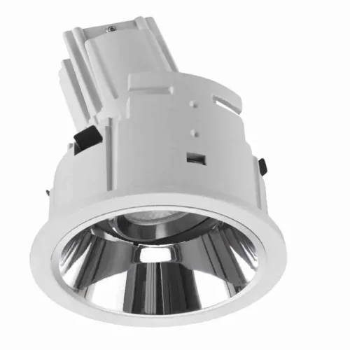
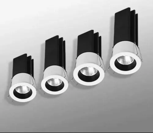
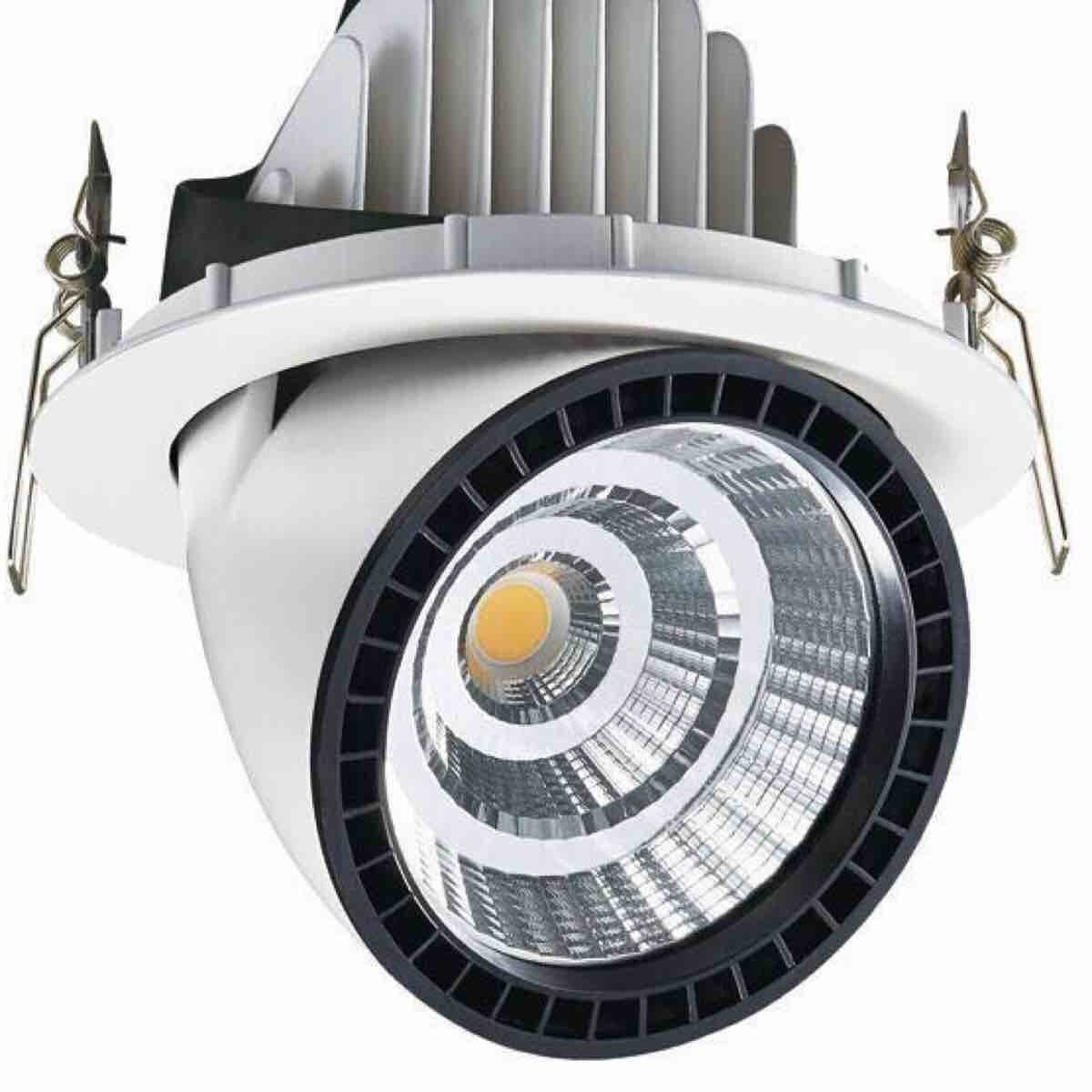
An LED zoomer light is not a universal technical category. On site, it usually means a spotlight with a movable lens that changes the beam angle, but the name may also describe a recessed fixture, track light, or decorative fitting. Identify the actual construction before choosing a test method.
Inspect these parts with the circuit isolated:
- Read the fixture label and photograph the driver, LED module, colour temperature, wattage, beam range, IP rating, and dimming protocol. Record whether the driver is external, sealed, or potted.
- Check the lens and zoom mechanism for cracks, dirt, loose retaining rings, or binding. Inspect the housing, heatsink, thermal interface, LED board, connectors, polarity marks, and signs of heat damage.
- Examine the track adaptor, mounting hardware, wiring terminals, strain relief, and junction-box connections. Look for loose screws, scorched insulation, corrosion, and a fitting that sits loosely on the track.
- Switch off the MCB, isolate the circuit, verify absence of voltage with a suitable tester, and prevent re-energisation. The driver can retain capacitor charge after switch-off, so do not touch internal parts immediately.
- With covers secure and testing performed by a competent person, measure line-to-neutral at the fitting: India’s nominal supply is 230 V AC, 50 Hz. Check whether voltage collapses when other loads start; a loose neutral or overloaded circuit can mimic a failed light.
This is the safe starting point for how to troubleshoot led zoomer lights in hyderabad.
Trace the Fault from the MCB to the LED Module
Start at the MCB, not the LED board. Isolate the circuit before opening the fitting, verify that no voltage remains, and prevent re-energisation; a 230 V AC supply and a driver’s charged capacitors can remain hazardous after switch-off.
1. Check the MCB and measure line-to-neutral at the fitting while switched on. India’s nominal supply is 230 V, 50 Hz. A low or collapsing reading points to an overloaded circuit, loose neutral, poor termination, or incoming-power fault. Test the light on a known-good circuit.
2. Isolate power and inspect the track adaptor, terminal block, plug, and internal connectors. Tighten or replace heat-damaged terminals. Flickering, delayed starting, or intermittent operation that changes when the fitting is moved indicates a connection fault.
3. If the driver receives the specified input but the light stays dead, test its output against the driver label. Do not judge a constant-current driver with the LED disconnected: its open-circuit voltage is not its normal operating output. No output indicates a driver fault.
4. If the driver produces its specified output under the connected load, inspect the LED board, connector seating, polarity, thermal interface, and visible solder damage. A dark board indicates an LED-module fault; dim output or thermal shutdown points to poor heat transfer or a failing module.
For recurring LED zoomer light problems, bypass a dimmer or control device temporarily with a correctly rated switch. If the symptom disappears, check driver compatibility rather than replacing the LED. Record the driver’s current, voltage range, wattage, and dimming protocol before ordering parts.
Check Track Adaptors, Controls, and Driver Compatibility
A zoomer that runs normally on a plain switch but flickers, buzzes, drops out, or has a narrow dimming range on the control circuit has a control-compatibility problem until proven otherwise. A unit that fails under both conditions points to the driver, track connection, wiring, or LED assembly.
Use this isolation checklist:
- Isolate mains power, remove and reseat the track adaptor, and confirm its locking tab, contact pins, polarity selector, and current rating match the track. Test the fitting in a known-good track position with a known-good adaptor.
- Bypass the dimmer, 0–10 V controller, DALI system, PWM controller, or smart relay temporarily with a correctly rated switch. Restore power only after checking that the driver is suitable for 230 V, 50 Hz operation.
- Read the driver label. Match its output voltage range, constant-current value, wattage range, dimming method, minimum load, and control wiring. A non-dimmable driver on a phase-cut circuit can flicker or fail early; a phase-cut driver will not automatically work with DALI or 0–10 V.
- If the light becomes stable with the bypass switch, test or replace the control device with a compatible model. If it remains faulty on a known-good track and switch, suspect the driver.
- Fit an exact-compatible replacement driver for confirmation; matching wattage alone is insufficient. If the replacement works, retain the old driver’s model and output details in the service record.
Record the test method, adaptor position, control settings, and replacement part number. This prevents an incompatible hidden driver from causing the same call-out again.
Separate Optical, Mechanical, Thermal, and Moisture Faults
An electrically sound circuit does not prove that the light engine or zoom assembly is healthy. Isolate mains power before opening the fitting, then inspect the fault by location rather than replacing the driver immediately.
- Optical: An uneven beam, dark centre, glare, or changed beam angle points to a scratched, displaced, contaminated, or incorrect lens or optic. Check that the optic is seated squarely and that the beam changes evenly across the full zoom range.
- Mechanical: A sticking zoom indicates a jammed or misaligned lens barrel, contamination, a loose retaining ring, or contact with the heat sink. Move the mechanism gently with power isolated; do not force it, because a bent guide can permanently damage the optic. A loose barrel, retaining ring, or housing can also buzz through vibration.
- Thermal: Overheating, output reduction, or a colour change after several minutes indicates poor heat transfer, blocked airflow, loose thermal hardware, or a heat sink pressing against nearby material. Inspect the LED board’s thermal interface and compare operation cold versus warm; a fixture that recovers after cooling is entering thermal protection.
- Moisture: Condensation, green or white corrosion, water marks, or intermittent colour change indicate moisture ingress. Check the lens seal, cable entry, housing joints, and stated IP rating; dry the fitting and correct the ingress path before re-energising it.
Locate buzzing with a listening probe while the fitting is safely isolated between checks. If the noise comes from a vibrating driver, mounting part, or zoom barrel, tightening or replacing that part is different from repairing the LED module.
Decide Between LED Zoomer Light Repair and Replacement
Repair is practical when the LED zoomer light has a replaceable external driver, connector, optic, lens, or LED module. Replace the fitting when its electronics are sealed, potted, or thermally bonded, or when the zoom mechanism, housing, and heat path are damaged together; repeated failures will cost more than a matched unit.
Record the original specification before ordering parts. Matching wattage alone can produce flicker, colour shift, overheating, or a driver that destroys the LED.
- Isolate the circuit, verify absence of voltage with a suitable tester, and prevent re-energisation. A 230 V AC circuit remains dangerous, and driver capacitors can retain charge after switch-off.
- Require the LED zoomer light installer in Hyderabad to record incoming-voltage, driver-output, LED-module, dimming, and final operating tests. The output test must use the connected LED for a constant-current driver; an open-circuit reading can mislead you.
- Require written confirmation of driver model, current, voltage range, wattage, colour temperature, beam range, cut-out, IP rating, and dimming protocol.
- For a stretch ceiling, require checks of the mounting platform, weight support, strain relief, heat clearance, membrane separation, and driver access. The membrane must not carry the fitting or touch a hot heat sink.
- Before sign-off, demand an as-installed record showing fitting locations, driver access points, replacement part numbers, and building-control settings.
If The LightHouse is involved, ask for this record as part of handover, not after the first failed replacement. Operate every light through the actual dimmer or control system before closing the ceiling or access panels.
Related product
 | ₹3500 LED zoomer for retail showrooms View product → |
Frequently asked questions
What should you check first when an LED zoomer light fails?
Identify whether it is a track, recessed or surface-mounted fitting, then isolate the circuit at the MCB and confirm the absence of voltage before inspection.
How do you trace an LED zoomer light fault?
Check the supply at the MCB, junction box and fixture terminals, then test the track adaptor, driver input and output, and LED module in that order.
Why does an LED zoomer light flicker or fail on a track?
Inspect loose track contacts, an incorrectly positioned adaptor, incompatible dimming controls, and a driver whose voltage, current or dimming protocol does not match the module.
When should you repair or replace an LED zoomer light?
Repair a replaceable adaptor, driver or connection when the fixture remains safe and compatible. Replace it when the LED board, sealed housing, optics or enclosure has heat or moisture damage.
Keywords